









Quick Answer
Four things decide whether a check valve works or fails: flow direction arrow, straight pipe run distance, valve type matched to orientation, and distance from the pump. This check valve installation guide covers all four across swing, lift, wafer, and dual-plate check valve types. YKY Valve manufactures API 594 and GB/T 12236 certified swing check valves for 100+ global OEM clients across water treatment, oil and gas, and chemical industries with 100% pressure testing before shipment and delivery across 30+ countries.
What Are the Core Installation Requirements?
These apply before touching the valve. All of them. Every time.
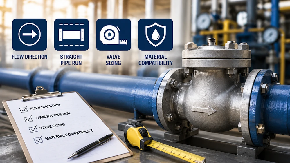
Flow direction
The check valve flow direction arrow on the valve body points in the direction fluid is allowed to travel. That arrow is the only orientation guide. Do not assume based on valve position or pipe layout. Confirm the arrow matches pipeline flow before positioning the valve.
Straight pipe run
Where to install check valve in pipeline matters as much as how. Per MSS SP-92: five pipe diameters of straight run upstream, ten downstream from pumps, tees, fittings, and increasers. From elbows: three to five pipe diameters minimum. Turbulent flow from nearby fittings causes disc flutter. Flutter wears the pin connections. Eventually the disc cannot seat properly and the valve fails.
Valve sizing
Size for actual operating flow. Not future expansion. An oversized valve in low-flow conditions sits nearly closed. The disc oscillates. Pin connections wear through vibration until the disc fails to close.
Material compatibility
Match valve body material to the pipeline. Dissimilar metals cause galvanic corrosion at the joint. Brass with copper pipelines. Stainless steel and copper are not directly compatible without an intermediary fitting between them.
What Are the Orientation Rules by Valve Type?
Check valve installation vertical or horizontal capability is not the same across valve types. The table below maps each type to acceptable orientations before you order.
| Valve Type | Horizontal | Vertical Upward | Vertical Downward |
| Swing check valve | Standard | Low velocity only | Not acceptable |
| Lift check valve | Standard | Acceptable | Not acceptable |
| Wafer dual-plate check valve | Standard | With spring assist | Not acceptable |
| Spring-assisted axial check valve | Standard | Both directions | Acceptable |
| Ball check valve | Standard | Upward flow only | Not acceptable |
Check valve installation direction for swing check valves means horizontal pipelines in most conditions. The disc relies on gravity to close when flow stops. In vertical upward flow at low velocity, gravity does not close the disc fast enough. Slow closure. Water hammer follows. Spring-assisted axial designs are the correct call when vertical installation is unavoidable.
For wafer-style valve specifics, the wafer check valve installation guide covers hinge pin orientation, gasket selection, and bolt tightening sequence in full detail.
How Do You Install a Check Valve Step by Step?
How to install check valve correctly. Six steps. Follow them in order.
Step 1:
Shut off the fluid supply. Never install into a live pressurized system. Confirm upstream isolation first.
Step 2:
Inspect the valve. Push the disc by hand. Both directions. Must move freely. No sticking. No debris on seating faces. No damage to the sealing surface. Clean the pipeline and valve connection faces before fitting.
Step 3:
Confirm flow direction. Check the check valve flow direction arrow. Matches pipeline flow. Do this before positioning the valve. Not after.
Step 4:
Position and connect. Valve at the correct location. Adequate straight pipe run on both sides confirmed. Flanged connections need gasket material matched to the media and crisscross bolt tightening in three torque passes. Threaded connections need PTFE tape or thread sealant on male threads.
Step 5:
Pressure test. Restore fluid supply. Bring the system to operating pressure. Inspect every connection point. No drips. No wet surfaces on any joint.
Step 6:
Functional check. Forward flow opens the disc smoothly. Flow reversal closes it without water hammer. Loud slamming means oversizing or insufficient straight pipe run. Not a valve defect. A system design problem.
What Are the Most Common Installation Mistakes?
Five mistakes. All avoidable. All common.
Too close to the pump.
High-velocity discharge focuses a jet directly on the disc and pin connections. Accelerated wear. Premature disc failure. The disc stops seating properly long before the valve’s rated service life. Keep the minimum straight pipe run between pump discharge and valve.
Wrong valve type for the orientation.
Swing check valve in a vertical downward flow pipeline. Disc cannot close against gravity. Backflow every time. Confirm valve type suitability for the orientation before purchase.
Oversizing for future expansion.
Valve operating at 17 degrees open under low flow. Disc oscillates. Pin connections grind down. Disc fails to seat. Size for current actual flow, not anticipated peak demand.
Ignoring the flow arrow.
Valve installed reversed. Disc opens against backflow. Blocks forward flow. System fails immediately. The arrow is the only guide.
Installing near elbows or reducers without adequate distance.
Turbulent eddies from nearby fittings create unsteady disc loading. Flutter. Wear. Improper seating. Maintain the minimum straight run from all upstream and downstream fittings. No exceptions.
Why Choose YKY Valve for Check Valve Supply?
API 594 and GB/T 12236 certified. WCB, CF8M, LCB body materials. Metal-to-metal and elastomeric seat options. PN16 to PN64. 1″ to 24″ size range. 100% pressure-tested before shipment. Factory-direct. No strict MOQ. Single-piece samples available.
For help selecting the correct check valve type before installation, the industrial check valve selection guide covers valve style, sizing, and media compatibility. For the full YKY range including API and GB swing check configurations, browse YKY’s check valve product page. For project-specific technical support, contact YKY Valve for engineering consultation.
Engineered for high-pressure pipelines, this API swing check valve features a durable swing disc and metal-to-metal seal—ideal for oil refineries, power plants, and steam systems.
Explore Product
Frequently Asked Questions
What is the minimum straight pipe run for check valve installation?
Five pipe diameters upstream and ten downstream from pumps, tees, and increasers per MSS SP-92. From elbows, minimum three to five pipe diameters. Shorter distances increase disc flutter and accelerate wear on disc pin connections.
Can a swing check valve be installed vertically?
Only with upward flow at sufficient velocity to hold the disc open. Vertical downward flow is not acceptable for swing check valves. Spring-assisted axial designs are the correct specification when vertical installation in either direction is required.
How do I find the correct flow direction for check valve installation?
Check the arrow marked on the valve body. It points in the direction of permitted fluid flow. Always verify this arrow against actual pipeline flow direction before positioning or connecting the valve in the pipeline.
What causes water hammer in check valve systems?
Oversized valves closing from a nearly shut position, insufficient straight pipe run creating turbulent flow, or slow disc closure on vertical installations. Correct sizing, adequate pipe run, and spring-assisted designs reduce water hammer risk significantly.